Patents
Medical film illuminator
Patent number: 6817738
Abstract: A medical film illuminator includes a frame having a translucent panel. A film gripper is attached directly to the translucent panel and the translucent panel is attached to the frame using magnets that engage the frame. Thus, the translucent panel can be easily removed to service the interior of the frame. Moreover, the spacing between the gripper and panel is established during manufacture and does not change, thus ensuring that gripping tension on film that is slid between the gripper and panel remains constant during the life of the illuminator.
Type: Grant
Filed: May 6, 2002
Date of Patent: November 16, 2004
Assignee: Wolf X-Ray Corporation
Inventors: William P. Winters, David Kaplan
Camera cap for an intra oral camera
Patent number: 6654552
Abstract: A camera cap for an intra oral camera includes a base plate from which a first side plate and a second side plate extend. The base plate forms a hole. The camera cap establishes an interior surface on which an adhesive layer is disposed. The camera cap can be installed on the head of an intra oral camera to block any light produced by the head of the camera while allowing imaging of, e.g., an x-ray, through the hole in the base plate.
Type: Grant
Filed: September 11, 2002
Date of Patent: November 25, 2003
Assignee: Wolf X-Ray Corporation
Inventor: William P. Winters
Color coding method and apparatus for an X-ray positioning system
Patent number: 6033111
Abstract: Color coding the components of a dental positioner, including an aiming ring, a bite block and an indicator arm allows the operator to assemble the correct positioner for proper positioning and alignment according to a particular dental area to be X-rayed. The color coding corresponds to different dental areas including the anterior and posterior dental areas. For coronal areas, a bite-wing block is provided which also may be in the color coded.
Type: Grant
Filed: November 20, 1998
Date of Patent: March 7, 2000
Assignee: Wolf X-Ray Corporation
Inventors: William Winters, Howard Wolf
Film cassette
Patent number: 3942016
Abstract: A cassette for holding radiographic film in which the edges of the cassette are provided with identifying indicia in accordance with a preselected code. The cassette includes a rectangular front panel facing one side of the film and a removable back panel facing the opposite side. This latter panel is provided with a lead coating and a layer of felt on the surface adjacent the film. The back panel serves as a cover for the cassette and is held in place by a pair of leaf springs which are supported for pivotal movement intermediate their ends. A hollow rectangular frame is disposed about the periphery of the panels, and each edge of the frame includes an indentation in close proximity with but spaced from one of the adjacent corners of the frame. Each of the indentations carries coded identifying indicia mounted entirely within the indentation.
Type: Grant
Filed: June 29, 1971
Date of Patent: March 2, 1976
Assignee: Wolf X-Ray Corporation
Inventor: Joseph S. Schatz
X-Ray Protective Apron:
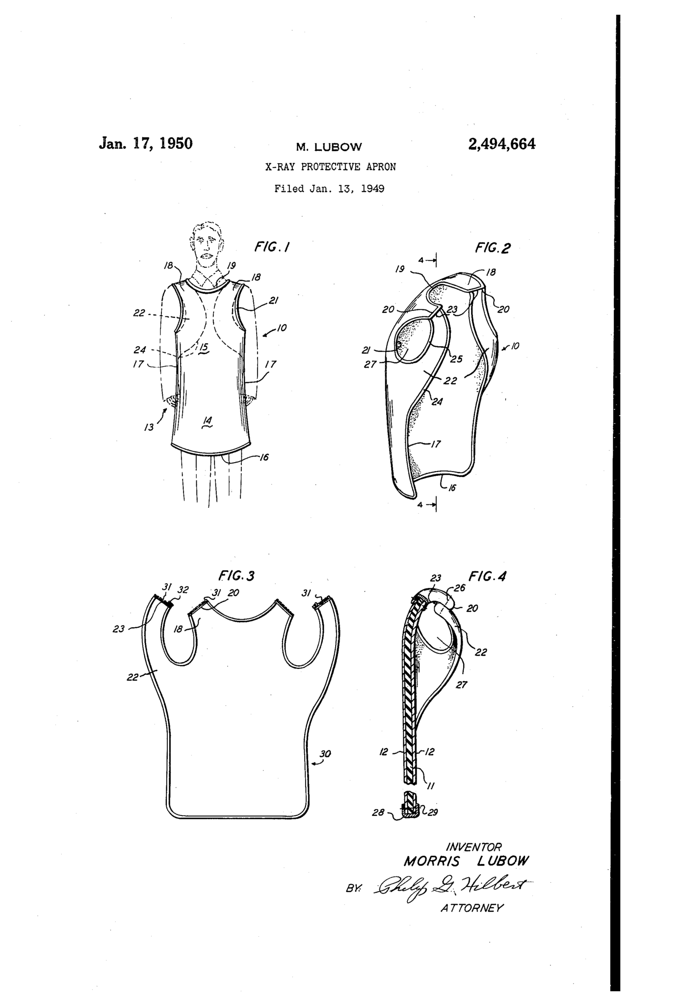 |
Jan. 17, 1950 n M LUBQW 2,494,664 X-RAY PROTECTIVE APRON Filed Jan. 13, 1949 INI/EN TOR M ORP/S l. UB OW A TTORNEV Patented `ian. 17, 1950 2,494,664 x-RAY PROTECTIVE ArRoN Morris Lubow, Long Beach, N. Y., assignor to Wolf X-Ray Products, Inc., New York, N. Y. Application January 13, 1949, Serial No. 70,6794 Claims. (Cl. Z50-108) This invention relates to protective garments. More particularly it concerns aprons which protect the wearer against the harmful action of X-rays. yet permitting the split portions to be detached when the apron is not in'use, thus allowing the apron to be stored in a fiat condition thereby eliminating the possibility' of cracking of the X-ray protective aprons have been made which 5 sheeting at the bent portions of the apron strucinclude one or more sets of straps, strings or the ture. like for retaining the apron in conformed relation Still another object of this invention is to to the body of the wearer. In addition to the provide an X-ray protective apron which may be problem of attaching such straps or strings to the worn with either surface exposed, which is of apron, there is also the inconvenience of tieing and simple construction, is economical to manufacuntieing the straps or strings. Accordingly, an ture, is of pleasing appearance and yet is pracobject of this invention is to provide an improved tical and eicent to a high degree in use. apron which is designed to be wornwithout the Other objects of this invention will in part be need for straps or strings to keep the apron in obvious and in part hereinafter pointed out. conformed relation to the body of the wearei` and The invention accordingly consists in the feawhich is adapted to be applied or removed from tures of construction, combinations of elements, the body of the wearer with a minimum number and arrangement of parts, which will be exemplie of motions. ed in the construction hereinafter described, |
Another object of this invention is` to provide an and of which the scope of invention will be indiimproved X-ray protective apron made from cated in the following claims. flexible sheeting loaded with heavy materials In the accompanying drawings, in which lis which are opaque to X-rays, the apron being deshown illustrative embodiments of the invention: signed to more uniformly distribute the weight of Fig. 1 is a front elevational view of an apron the apron as a whole relative to the shoulders of embodying the invention and being worn by the the wearer, whereby the apron may be worn with wearer; maximum comfort. Fig. 2 is a rear perspective view of the apron;
A further object of this invention is to provide Fig. 3 is a front elevational view of an apron an improved X-ray protective apron made from embodying the invention and illustrating a modian integral sheet of rubber or plastic loaded with iication thereof, with the shoulder covering and heavy material opaque to X-rays, and compriswing portions detached from each other and ing a front body covering portion and a pair of Fig. 4 is a sectional view taken on the line 4-4 back covering portions, the last mentioned por- 0f Fig. 2. tions being adapted when the apron is being worn, Referring in detail to the drawings, I0 desigto curve the front body covering portion into nates an X-ray protective apron embodying the closely conforming relation to the hips and thighs invention. The same is formed from an integral as well as the frontal portions of the wearer, flexible, rubber or plastic sheeting II which without the need for retaining straps or strings. is initially comDOlmded With materiels Which Will Yet another object of this invention is to prorender the sheeting opaque to X-rays, such as Vide an X-ray protective apron made from a lead, lead oxide or other suitable materials havloaded rubber or plastic sheeting which comprises ing similar properties. The compounded rubber a frontal body covering portion and a pair of latsheeting is of substantial unit weight which erally and upwardly extending portions which varies with the proportionate amount of opaciinterconnect laterally spaced portions of the filing material inlOdU-Ced into tfhe Sheetupper end of the frontal body covering portion The sheeting II is covered on either surface with opposed side edge portions of the frontal thereof with a sheet textile fabric I2, such as body covering portion to form a pair of shoulder stockinette or the like. The fabric I2 may be covering portions and a pair of arm holes, the suitably adhered to the sheet II by means of laterally and upwardly extending portions formcement or the like. ing transversely bent or curved portions at the The composited material II, I2, is suitably cut juncture thereof with the frontal body covering to provide a frontal body CGVeI'iIlg DOItGn I3 0f portion, the laterally and upwardly extending generallyv rectangular shape. The portion I3 portions being split transversely at their junccomprises a lower skirt portion I4 and an upper ture points or at a, point intermediate the juncportion I5 extending upwardly therefrom. The ture points, the adjacent split portions being deskirt portion I4 includes a bottom edge I6 and tachably attached when the apron is being worn vertical side edges I1'. The dimensions of the portion I3 may be such that when the apron is worn, the bottom edge IE may be disposed below the knees of the wearer and the side edges I'I are well wrapped about the hips, thighs and legs of the wearer to aord the maximum protection against the effect of the X-rays.
The upper portion I5 comprises a pair of relatively wide shoulder covering portions I3 integral therewith and which extend upwardly from laterally spaced portions of the top edge thereof. The portions I8 are interconnected at their inner side edges by the intermediate, concavely curved neckline edge I9. Each of the portions I8 terminates in a transverse linear edge 20 with an inwardly and concavely curved outer edge 2l extending downwardly from the outer end of edge 20.
Extending outwardly and upwardly from the opposite sides of the portion I5 at the lower ends thereof and integral therewith, are a pair of similar wing or shoulder blade covering portions 22. Each of the portions 22 terminates at its upper end in a transverse linear edge 23v which is of a width substantially equal to that of the edges 2Q onY portions I8. Each of the portions 22 comprises an outer, convexly curved edge 24 which extends downwardly from the outer end of edge 23 and merges at its lower end with side edge Il. Each portion 22 also comprises an inner, concavely curved edge 25 which extends downwardly from the inner end of edge 23 and merges at its lower end with the lower end of edge ZI. The portions 22 may increase in width progressively from the edge 23 towards the juncture of the portion 22 with portion I5.
In forming the apron I0, each of the wing portions 22 is turned inwardly towards the back surface of body covering portion I3, thus bringing the terminal edge 23 opposite a terminal edge 20 of a shoulder covering portion I8. Each pair of edges 20, 23 is overlapped and secured together by a transverse seam 26, thus forming a pair of armholes 2'I with edges 2I, 25 deiining the openings.
The peripheral edges of the body covering portion I3 as well as portions I8, 22, may be bound with a U-shaped marginal binding 28 secured in place by stitching 2S, to give a finished appearance to the apron.
To apply the apron, it is only necessary for the wearer to extend his arms through the armholes 2l. The wing portions 22 will automaticallyassume their normal shoulder blade covering position, as indicated in the dotted lines in Fig. 1.
The portions 22 will not only lie ilat against the 1 back of the wearer but will also pull on the side edges oi' the body covering portion I3 as well as on the shoulder covering portions I8. The body covering portion I3 and the shoulder covering portions I8 will thus be closely conformed to the body of the wearer and retained in such conformed relation. It will be apparent that the side edge portions of the body covering portion I3 will `be well wrapped about the hips, thighs and legs of the wearer to afford maximum protection against the harmful effects of the'X-rays.
It has been found that due to the surface eX- tent and weight of the wing portions 22, the frontal body covering portion I 3 and the shoulder covering portions i8 are retained closely against the body of the wearer, despite the fact that the edges 24 of portions 22 diverge from each other, when the apron is worn, as shown in Fig. 1. Furthermore, it has been'found that the apron IIIv will be retained in body conforming relation a better distribution of the weight of the apron as a whole on either side of the wearers shoulders and thusV make the apron more comfortable to wear.
The apron may be removed readily and quickly by merely slipping the arms out of the armholes 21 and without the need for rst unfastening strings or straps.
In the event that the outer fabric I2 becomes unduly worn, the apron as a whole may be turned inside out and worn with the inner fabric I2 exposed.
In Fig. 3 is shown an apron 30 embodying the invention and illustrating a modification thereof. The apron 36 is similar to apron IB except as hereinafter described. In lieu of stitching the overlapped edges 20, 23 of the portions I8, 22, the edges 20, 23 are provided with slide fastener operated closure elements 3l which may be detachably interconnected by means of slide fastener 32. When the apron 38 is not in use and it is desired to store the same, each pair of connected portions I8, 22, are detached by means of slide. 32, thus allowing the portions I8, 22 to be extended and to lie. in the plane of the body covering portion I3, as shown in Fig. 3. The apron 30 may then be stored in a completely flat condition without danger of cracking the plastic or rubber sheeting II at the otherwise bent over portions formed by the juncture of the wing portions 22 with the body covering portion I3 and the bent over portion formed by the juncture of wing portions 22 with shoulder covering portionsY I8.
It is understood that the wing or shoulder blade covering portions 22 may be in the form of separate members and of a material similar to that of the body covering portion I3. In such case the portions 22 are seamed to the body portion I3.
It will thus be seen that there is provided a garment and modifications thereof, in which the several objects of this invention Iare achieved and which is well adapted to meet the conditions of practical use.
As various possible embodiments might be made of the above invention, and as various changes might be made in the embodiments set forth, it is to be understood that all matter herein set forth or shown in the accompanying drawings, is to be interpreted as illustrative and not in a limiting sense.
Having thus described my invention, I claim as new and desire to protect by Letters Patent:
l. An X-ray protective apron comprising flexible, plastic sheet loaded with heavy material opaque to X-rays, said sheet comprising a frontal body covering portion, a pair of shoulder covering portions of the same material as said body covering portion extending from laterally spaced upper ends of said body covering portion andV a pair of wing portions extending outwardly and upwardly from opposite side edges of said body covering portion, the terminal end of each wing portion being connected to the free end of one of the pair of shoulder covering portions integral with posed flat in contact with portions of the back of the wearer, thereby curving said frontal body covering portion and said shoulder covering portions into conformation with the body of the wearer and to retain said body and shoulder covering portions in body conforming condition in the absence of supplemental securing means.
2. An X-ray protective apron as set out in claim l, wherein each of said wing portions comprises Ia convexly curved outer edge extending from the terminal edge thereof to the side edge of said body covering portion whereby said curved edges are disposed in divergent relation to each other at their lower ends when the apron is being worn.
3. An X-ray protective apron as set out in claim 1, wherein each pair of wing and shoulder covering portions are detachabli7 attached to each other.
4. An X-ray protective apron comprising a weighted exible sheet of rubber which is opaque to X-rays, said sheet being substantially rectangular in shape and comprising a bottom edge, a pair of side edges extending from said bottom edge and a concavely curved top edge portion, a said sheet and extending therefrom on opposite sides of said curved edge portion, each of said shoulder covering portions terminating in a transverse linear edge, a wing portion of weighted flexible rubber extending outwardly and upward- V.ily from each of the side edges of said sheet at opposed points intermediate the bottom and top edges of said sheet, each of said wing portions .edge of each of said wing portions being attached to the terminal edge of one of said shoulder covering portions, the width of each wing portion '.Lfincreasing progressively from its terminal por- Number 'z tion toward its juncture with the side edge of said Sheell MORRIS LUBOW.
REFERENCES CITED The following references are of record in the file of this patent:UNITED STATES PATENTS Name Date 2,404,225 Green July 16,1946